
3D Printing vs CNC Machining: The Engineering and Cost Guide
In modern product development and rapid prototyping, choosing the right production workflow determines whether a hardware project stays on schedule or stalls in development limbo. Two digital manufacturing technologies lead this sector: additive manufacturing and computer numerical control subtractive machining. While both processes interpret digital computer-aided design (CAD) files to create functional physical components, their underlying mechanical physics, material properties, economics, and lead times are fundamentally different.
When evaluating 3D printing vs CNC machining, design engineers, product managers, and entrepreneurs are not simply picking a machine tool. They are deciding how material is shaped, how stresses are distributed across molecular bonds, how rapidly design iterations can be tested, and how unit costs behave as production scales.
Understanding the technical boundaries of each discipline ensures your prototypes validate mechanical assumptions accurately and transition smoothly into production.

AI Quick Answer: Core Manufacturing Differences
Direct Answer for Search & Decision-Makers:
3D printing is an additive manufacturing method that constructs parts layer-by-layer from filament, resin, or metal powder. It requires zero custom tooling, accommodates complex internal geometries and hollow structures, and delivers cost-effective single-unit prototypes within 24 to 48 hours. Conversely, CNC machining is a subtractive fabrication method that utilizes high-speed cutting tools to mill, turn, or drill solid billets of metal or engineering plastic. CNC machining provides tighter dimensional tolerances (±0.001 in / ±0.025 mm), superior isotropic mechanical strength, polished surface finishes (Ra 0.8–3.2 µm), and lower per-part costs at medium-to-high production volumes.
Quick Reference: 3D Printing vs CNC Machining Comparison Matrix
The comparative matrix below outlines the critical operational benchmarks between additive and subtractive manufacturing methods:
| Engineering Parameter | Industrial 3D Printing (Additive) | Precision CNC Machining (Subtractive) |
| Material Formation | Layer-by-layer addition (FDM, SLA, SLS, SLM) | Precision material removal from solid billets |
| Dimensional Tolerances | ±0.005 in to ±0.015 in (±0.1 to ±0.38 mm) | ±0.001 in to ±0.005 in (±0.025 to ±0.127 mm) |
| Surface Finish (Ra) | 3.2 – 12.5 µm (Visible layer lines unless post-processed) | 0.8 – 3.2 µm (Smooth as-machined; optical polishes possible) |
| Mechanical Integrity | Anisotropic (Weaker tensile strength along the Z-axis) | Truly Isotropic (Uniform physical strength across all axes) |
| Geometric Freedom | Near-limitless (Internal channels, honeycombs, organic lattices) | Constrained by tool access, cutter reach, and undercut angles |
| Material Waste | Minimal (Only supports and unbonded sintered powder) | Moderate to High (Subtractive swarf and chips) |
| Setup & Programming | Minimal (Automated slicing software; 10–15 min setup) | Significant (CAM toolpath generation, workholding, fixturing) |
| Economic Sweet Spot | 1 to 20 units (Prototypes, bridge production) | 20 to 10,000+ units (Scalable low-to-medium runs) |
Process Mechanics: Additive vs. Subtractive Principles
To understand how each method behaves under stress, one must inspect how the raw material transforms into the final component.
The Additive Architecture (3D Printing)
Additive manufacturing compiles an object by depositing or fusing raw feedstock layer upon layer. In fused deposition modeling (FDM), molten thermoplastic extrudes through a heated nozzle. The Stereolithography (SLA), a ultraviolet laser cures liquid photopolymer resin into hardened plastic. In selective laser sintering (SLS) and direct metal laser sintering (DMLS), focused lasers fuse microscopic nylon or metal particles together.
Because the process builds upward from an empty build plate, it requires no physical tool engagement or cutting fluids. Engineers can consolidate multi-piece assemblies into single monolithic parts. However, because each layer must chemically or thermally adhere to the preceding layer, printed parts often exhibit anisotropic properties meaning their structural tensile strength along the vertical build axis (Z-axis) is lower than along the horizontal planes (X and Y axes).
The Subtractive Architecture (CNC Machining)
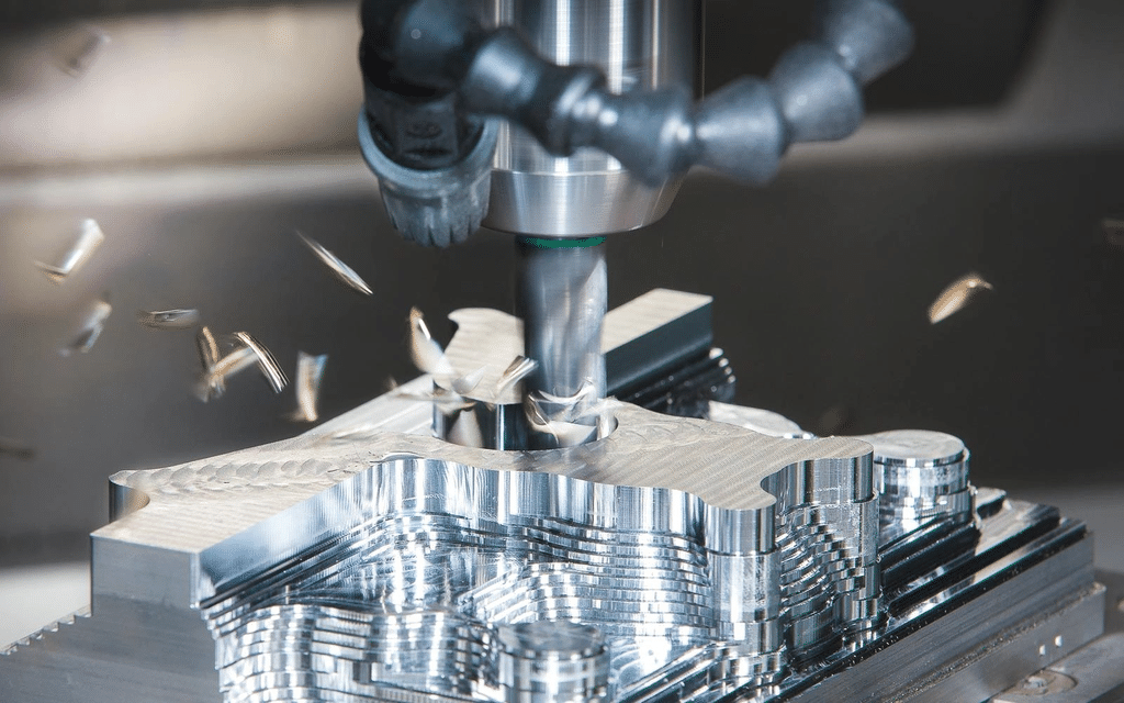
CNC machining starts with an oversized block, bar, or rod of certified stock material. Computer numerical control systems guide rotating cutting endmills (milling) or spin the workpiece against stationary cutters (lathe turning) to systematically carve away unwanted stock until the finished geometry emerges.
Because CNC parts are carved directly out of extruded, cast, or forged stock, they retain the raw material’s dense crystalline grain structure. The resulting components are isotropic, exhibiting uniform tensile, shear, and impact strength in every geometric direction. The trade-off lies in physical tooling constraints: cutting heads cannot turn square internal corners, reach deep narrow pockets without tool chatter, or carve completely enclosed internal channels.
Material Capabilities and Mechanical Performance
Material selection often decides the debate between additive and subtractive workflows. Both technologies handle polymers and metals, but they process them in very different forms.
Engineering Plastics
- In 3D Printing: Engineers commonly deploy PLA, ABS, PETG, TPU, and nylon. Advanced industrial printers also run high-performance polyetheretherketone (PEEK) and PEKK. While these materials perform well for form checks and functional enclosures, printed plastics typically display micro-porosities that make them unsuited for high-pressure pneumatic or fluid-sealing environments.
- In CNC Machining: CNC mills process practically any machinable engineering polymer, including Delrin (acetal), PTFE (Teflon), UHMW-PE, PEEK, polycarbonate, and acrylic. Machined plastics feature exceptional surface finishes, dimensional stability under thermal load, and tight seals for fluidic manifolds.
Structural Metals
- In 3D Printing: Metal 3D printing (SLM/DMLS) utilizes atomized powders of titanium (Ti64), aluminum (AlSi10Mg), stainless steel (316L), and Inconel. While modern metal printers produce dense parts, components almost always require post-build thermal stress-relief cycles in a furnace, support removal via wire EDM, and secondary CNC machining across mating faces to achieve precise tolerances.
- In CNC Machining: CNC equipment easily cuts through billet aluminum (6061, 7075), stainless steel (303, 304, 316), brass, copper, bronze, and hardened tool steels. According to standards published by the National Institute of Standards and Technology (NIST), certified billet stock provides traceable metallurgy, predictable fatigue thresholds, and consistent grain structure required for mission-critical aerospace and medical device hardware.
Cost Analysis: Analyzing the Financial Breakeven Point
Understanding 3D printing vs CNC machining costs requires separating fixed machine preparation expenses from variable per-unit material costs.
The Cost Dynamics of 3D Printing
3D printing operates on a nearly flat cost curve. Slicing an STL file takes minutes, and zero custom jigs or cutting tools are needed before production starts.
- Unit 1 vs. Unit 50: Printing a single housing costs virtually the same per unit as printing fifty housings.
- Geometric Freedom: A part with intricate internal pockets, varied wall thicknesses, and organic contours costs the same to print as a simple solid cube of identical volume.
- Limitation: As batch sizes grow into hundreds of units, print speeds cannot compete with high-speed automated machine centers, making mass production economically inefficient.
The Cost Dynamics of CNC Machining
CNC machining carries high upfront non-recurring engineering (NRE) costs. An experienced programmer must import CAD geometry into computer-aided manufacturing (CAM) software, define spindle speeds, program feed rates, plan toolpaths, and select rigid clamping fixtures. Setting up the machine, aligning work coordinate systems, and running test parts requires dedicated skilled labor.
- Upfront Hurdle: A single custom CNC bracket might cost $300 to $500 due to initial programming and fixturing overhead.
- Volume Scaling: Once the G-code program is proven and jigs are locked in, each subsequent part cycles through the machine in minutes. Spreading that fixed setup cost over 50 or 500 parts drops the individual price down to $25 or $15 each.
- Geometric Penalties: Complex geometries requiring multiple axis setups, custom soft jaws, or specialized long-reach endmills increase machine cycle times and drive up the final quote.
For engineers seeking tailored product development cycles and agile part production, working with experienced manufacturing partners like Wild Designs ensures you select the correct fabrication method before cutting metal or queuing build plates.
Tolerances, Surface Finish, and Post-Processing
Dimensional precision determines how components assemble into complex physical mechanisms.
Tolerances and Repeatability
Precision CNC milling routinely holds tight tolerances within ±0.001 inches (0.025 mm), with high-end wire EDM and grinding processes achieving sub-micron accuracy. This degree of dimensional fidelity is essential for bearing press fits, dynamic shaft couplings, dowel pin locations, and O-ring sealing grooves.
Industrial 3D printers typically maintain tolerances between ±0.005 and ±0.015 inches (0.127 to 0.381 mm). While high-resolution SLA resin printers achieve finer cosmetic details, thermal shrinkage, material cooling, and mechanical backlash in belt-driven axes introduce dimensional variations that can cause interference issues in tight multi-part mechanical assemblies.
Surface Texture and Roughness
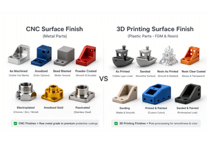
As-machined CNC parts emerge with clean toolpath patterns and an average surface roughness (Ra) between 0.8 and 3.2 micrometers. They can be readily bead-blasted, anodized, passivated, or electro-polished.
Conversely, 3D printed parts display step-like striations along curved surfaces known as the “stair-stepping effect.” Eradicating these layer lines requires labor-intensive secondary post-processing, such as manual wet sanding, vapor smoothing with chemical solvents, primer coats, or secondary CNC fly-cutting across critical datum faces.
Environmental Impact and Material Waste
Sustainability profiles between the two methods mirror their fundamental mechanics:
- Subtractive Waste: CNC milling frequently transforms 40% to 80% of a raw metal billet into scrap chips. While high-grade machine shops collect, clean, and recycle aluminum and steel chips, the recycling cycle consumes additional energy to remelt and re-cast the alloys.
- Additive Efficiency: 3D printing adds material only where structural load demands it. Advanced lightweighting techniques, such as topological optimization and internal gyroid infills, yield lightweight structures that save material during manufacturing and reduce fuel consumption in final automotive and aerospace applications.
Decision Framework: When to Choose Each Method
Use this clear checklist to determine which manufacturing process best suits your hardware release schedule:
Choose 3D Printing When:
- You are in early concept validation: You need an ergonomic handheld mockup or aesthetic design review model within 24 to 48 hours.
- Geometries are impossible to machine: The design incorporates internal cooling passages, organic topological skeletons, or curved hollow volumes.
- Production volume is extremely low: You only require 1 to 10 visual models or custom functional brackets.
- Assembly consolidation is a priority: You wish to combine multiple individual fasteners and sheet-metal brackets into one unified print.
Choose CNC Machining When:
- Critical mechanical tolerances are required: Shaft journals, threaded bearing bores, and precision sliding fits demand sub-thousandth-of-an-inch accuracy.
- Structural isotropic strength is non-negotiable: The part endures dynamic cyclic stresses, pressurized liquids, high torsional torque, or intense impacts.
- You require production-grade surface finishes: The component functions as an optical faceplate, consumer enclosure, or fluid-tight mating surface.
- Batch volume spans dozens to thousands: You need 25 to 5,000 components where volume scaling lowers the per-unit cost below additive techniques.
The Modern Solution: Hybrid Manufacturing
Engineering teams are rarely forced into a strict binary choice. Many successful operations utilize a hybrid approach.
During early development stages, teams rapidly iterate three or four design variations on industrial 3D printers, testing fit and layout at minimal expense. Once the design envelope stabilizes and functional load testing begins, the CAD model transfers into CAM software for precision CNC machining in billet aluminum or stainless steel. In advanced aerospace manufacturing, complex metal brackets are increasingly printed using DMLS near-net shape technology, and then transferred to a 5-axis CNC mill to machine critical mating datums, bearing journals, and threaded holes to exact tolerances.
Conclusion
Understanding 3D printing vs CNC machining is not about finding a single superior tool, but about matching the manufacturing process to your project’s lifecycle phase. By pairing the rapid, unconstrained geometric freedom of additive manufacturing during early concept development with the structural durability, surface quality, and tight tolerances of subtractive CNC machining during production, you can accelerate innovation and deliver reliable, high-performance mechanical products.